Intermatic T104r201 Wiring Diagram
Intermatic T104p201 Instruction Manual T104r201

How To Wire Intermatic T104 And T103 And T101 Timers
Intermatic T104r201 Wiring Diagram Wiring Diagram

Intermatic Pool Timers

Wiring Diagram For T104 Pool Timer How To Wire Intermatic Timer

Photos Of Wh40 Timer
For large loads such as air conditioners spas and.
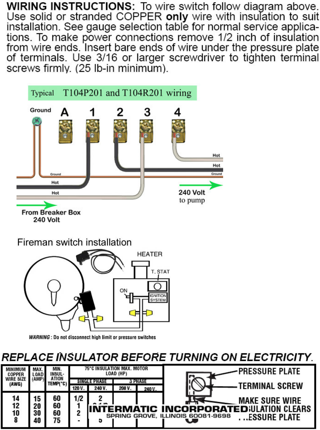
Intermatic t104r201 wiring diagram. Model r8806p101c peter pa how to replace a intermatic 240v swimming pool timer mechanism chlorine king pool service duration. Dpdt switch spdt 6 terminal switch working in hindi. Check that the input voltage lines are connected to terminals 1 and 3 as shown in step 14. Swimming pool tips reviews how to spl 161 457 views.
Knockout dimensions bottom 2 1 2 and 3 4 knockout dimensions back side. Intermatic t100 series 40 amp 24 hour outdoor mechanical timer with double pole single throw switching 240 vac gray. Knockout dimensions bottom 2 1 2 and 3 4 knockout dimensions back side. Top suggestions e10694 pool timer wiring diagram.
11 videos play all troubleshooting our intermatic inc. By erika schulz on june 04 2020 in wiring diagram 240 views. Intermatic t104r201 time switch beige. E10694 pool timer wiring diagram.
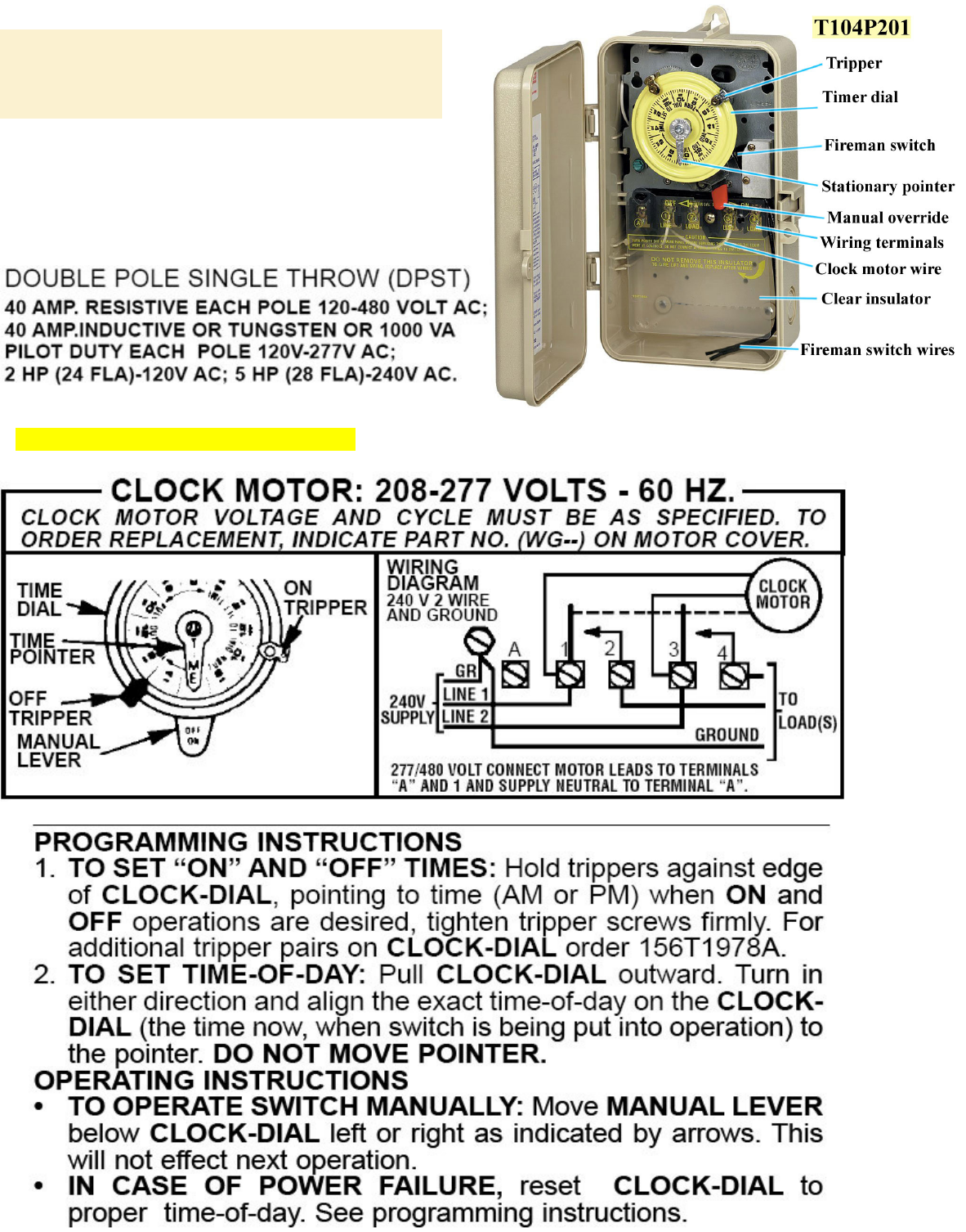
T104p201 24 hour mechanical time switch in enclosure with pool heater protection. Wiring slightly changed but the circuit diagram. Intermatic t104r201 wiring diagram homeoff1. Correct replacement for my older one 15 years with bad timer.
Intermatic t104r201 wiring diagram. T101r201 24 hour mechanical time switch in enclosure with pool heater protection. Intermatic t104p201 time switch by. Specifications and wiring diagrams for every can be wired as dpdt.
Intermatic t100 series mechanical time switches deliver long lasting value. Don t be alarmed when it arrives with none of the holes cutout for your wiring connections. Carol the t104 runs on 220v. Reviewed in the united states on march 18 2016.
Make sure your supply voltage to the timer is 220v. Intermatic t100 series mechanical time switches deliver long lasting value. E10694 pool timer wiring diagram. The intermatic intouch system helps homeowners set the scene for entertaining.

Intermatic T101r201 Instructions Assembly Manualzz

Intermatic T100 Series Timers With Parts Manuals And Wiring

Intermatic Timers And Manuals

Intermatic Pool Spa Time Switches Controls Timers

Http Waterheatertimer Org How To Wire T104 Intermatic Timer Html

Wrg 4500 Wiring Caravan Fridge Diagram

220 240 Wiring Diagram For A Intermatic T104r Timer With Images

How To Wire Intermatic T12404r

Control Pump Or Timer With Rain Sensor Http Waterheatertimer

Solved I Have A New T104r Intermatic Mechanical Time Switch Fixya

Amplifier Wiring Diagram Wiring Diagram
How To Replace An Intermatic T104 Clock Motor Inyopools Com

Marked Mg Td Wiring Harness Wiring Diagram
